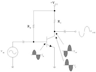
•DC biasing circuits
•DC and AC equivalent circuit
•Q-point (Static operation point)
•DC and AC load line
•Saturation Cutoff Condition
•Compliance
DC Biasing Circuits
•The ac operation of an amplifier depends on the initial dc values of IB, IC, and VCE.
•By varying IB around an initial dc value, IC and VCE are made to vary around their initial dc values.
•DC biasing is a static operation since it deals with setting a fixed (steady) level of current (through the device) with a desired fixed voltage drop across the device.
Purpose of the DC biasing circuit
•To turn the device “ON”
•To place it in operation in the region of its characteristic where the device operates most linearly, i.e. to set up the initial dc values of IB, IC, and VCE
Voltage-Divider Bias
•The voltage – divider (or potentiometer) bias circuit is by far the most commonly used.
•RB1, RB2
Þ voltage-divider to set the value of VB , IB
•C3
Þ to short circuit ac signals to ground, while not effect the DC operating (or biasing) of a circuit
(RE Þ stabilizes the ac signals)
® Bypass Capacitor
Graphical DC Bias Analysis
DC Load Line
•The straight line is know as the DC load line
•Its significance is that regardless of the behavior of the transistor, the collector current IC and the collector-emitter voltage VCE must always lie on the load line, depends ONLY on the VCC, RC and RE
•(i.e. The dc load line is a graph that represents all the possible combinations of IC and VCE for a given amplifier. For every possible value of IC, and amplifier will have a corresponding value of VCE.)
•It must be true at the same time as the transistor characteristic. Solve two condition using simultaneous equation
® graphically ® Q-point !!
Q-Point (Static Operation Point)
•When a transistor does not have an ac input, it will have specific dc values of IC and VCE.
•These values correspond to a specific point on the dc load line. This point is called the Q-point.
•The letter Q corresponds to the word (Latent) quiescent, meaning at rest.
•A quiescent amplifier is one that has no ac signal applied and therefore has constant dc values of IC and VCE.
•The intersection of the dc bias value of IB with the dc load line determines the Q-point.
•It is desirable to have the Q-point centered on the load line. Why?
•When a circuit is designed to have a centered Q-point, the amplifier is said to be midpoint biased.
•Midpoint biasing allows optimum ac operation of the amplifier.
DC Biasing + AC signal
•When an ac signal is applied to the base of the transistor, IC and VCE will both vary around their Q-point values.
•When the Q-point is centered, IC and VCE can both make the maximum possible transitions above and below their initial dc values.
•When the Q-point is above the center on the load line, the input signal may cause the transistor to saturate. When this happens, a part of the output signal will be clipped off.
•When the Q-point is below midpoint on the load line, the input signal may cause the transistor to cutoff. This can also cause a portion of the output signal to be clipped.
DC Biasing + AC signal
DC and AC Equivalent Circuits
Bias Circuit
DC equivalent circuit
AC equivalent circuit
AC Load Line
•The ac load line of a given amplifier will not follow the plot of the dc load line.
•This is due to the dc load of an amplifier is different from the ac load.
What does the ac load line tell you?
•The ac load line is used to tell you the maximum possible output voltage swing for a given common-emitter amplifier.
•In other words, the ac load line will tell you the maximum possible peak-to-peak output voltage (Vpp ) from a given amplifier.
•This maximum Vpp is referred to as the compliance of the amplifier.
(AC Saturation Current Ic(sat) , AC Cutoff Voltage VCE(off) )
AC Saturation Current and AC Cutoff Voltage
Amplifier Compliance
•The ac load line is used to tell the maximum possible output voltage swing for a given common-emitter amplifier. In another words, the ac load line will tell the maximum possible peak-to-peak output voltage (VPP) from a given amplifier. This maximum VPP is referred to as the compliance of the amplifier.
•The compliance of an amplifier is found by determine the maximum possible of IC and VCE from their respective values of ICQ and VCEQ.
Maximum Possible Compliance
Compliance
The maximum possible transition for VCE is equal to the difference between VCE(off) and VCEQ. Since this transition is equal to ICQrC, the maximum peak output voltage from the amplifier is equal to ICQrC. Two times this value will give the maximum peak-to-peak transition of the output voltage:
VPP = the output compliance, in peak-to-peak voltage
ICQ = the quiescent value of IC
rC = the ac load resistance in the circuit
When IC = IC(sat), VCE is ideally equal to 0V. When IC = ICQ, VCE is at VCEQ. Note that when IC makes its maximum possible transition (from ICQ to IC(sat)), the output voltage changes by an amount equal to VCEQ. Thus the maximum peak-to-peak transition would be equal to twice this value:
•Equation (A) sets the limit in terms of VCE(off). If the value obtained by this equation is exceed, the output voltage will try to exceed VCE(off), which is not possible. This is called cutoff clipping, because the output voltage is clipped off at the value of VCE(off).
•Equation (B) sets of the limit in terms of IC(sat). If the value obtained by this equation is exceed, the output will experience saturation clipping.
Cutoff and Saturation Clipping


