# Introduction
Some devices, such as transistors and amplifiers, act like controlled sources. For examples, the output voltage of an amplifier is controlled by the input voltage of that amplifier. Such devices can be modeled using dependent sources. A dependent source consists of two elements: the controlling element and the controlled element. The controlling element is either open circuit or short circuit and the controlled element is either voltage or current.
There are four types of dependent source that correspond to the four ways of choosing a controlling elements and a controlled element. These four dependent sources are
· Voltage-controlled voltage source (VCVS)
· Voltage-controlled current source (VCCS)
· Current-controlled voltage source (CCVS)
· Current-controlled current source (VCVS)
The modelings of these dependent sources are discussed in the next section.
# Voltage-controlled voltage source (VCVS)
The symbol of a Voltage-controlled voltage source (VCVS) is shown in Fig 1(a). N+ and N- are the positive and negative output nodes, respectively, and NC+ and NC- are the positive and negative nodes, respectively of the controlling voltage.

Fig-1
The description of VCVS is
E<name> N+ N- NC+ NC- g (gain value)
Typical statement
E1 1 2 3 4 2
The statement means that the VCVS E1 is connected between nodes 1 and 2 and its voltage is controlled by the voltage between nodes 3 and 4. The voltage gain is 2.
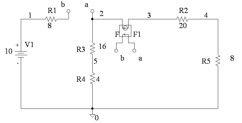
Now if for the circuit in Fig. 1(b) the italic numbers are parameter value and normal numbers are node number the Netlist may be written as
R1 1 2 8
R2 3 4 20
R3 0 4 8
R4 5 2 16
R4 0 5 4
E1 2 3 5 0 0.5
V1 1 0 10
Exercise 1
Try to write the Netlist of the following circuit
The description of VCVS is
E<name> N+ N- NC+ NC- g (gain value)
Typical statement
E1 1 2 3 4 2
The statement means that the VCVS E1 is connected between nodes 1 and 2 and its voltage is controlled by the voltage between nodes 3 and 4. The voltage gain is 2.
Now if for the circuit in Fig. 1(b) the italic numbers are parameter value and normal numbers are node number the Net list may be written as
R1 1 2 8
R2 3 4 20
R3 0 4 8
R4 5 2 16
R4 0 5 4
E1 2 3 5 0 0.5
V1 1 0 10
Exercise 1
Try to write the Net list of the following circuit

Fig-2
# Voltage-controlled current source (VCCS)

The description of VCCS is
G<name> N+ N- NC+ NC- g (transconductance value)
Typical statement
G1 1 2 3 4 2 z
The statement means that the VCCS G1 is connected between nodes 1 and 2 and its current is controlled by the voltage between nodes 3 and 4. The transconductance value is 2.
Now if for the circuit in Fig. 1(b) is redrawn by replacing the VCVS with a VCCS, we get the circuit in Fig 3(b) and the Netlist may be written as
R1 1 2 8
R2 3 4 20
R3 0 4 8
R4 5 2 16
R4 0 5 4
G1 2 3 5 0 0.5
V1 1 0 10
# Current-controlled current source (CCCS)
The symbol of a Current-controlled current source (CCCS) is shown in Fig 4(a). N+ and N- are the positive and negative nodes, respectively, of the current source. VN is a voltage source through which controlling current flows. The controlling current is assumed to flow from the positive node of VN through the voltage source VN to the negative node of VN.

Fig-4
The description of CCCS is
F<name> N+ N- VN g (current gain value)
Typical statement
F1 1 2 V1 1
The statement means that the CCCS F1 is connected between nodes 1 and 2 and its current is controlled by the voltage source V1’s current. The current gain value is 1.
So, the Netlist of the circuit shown in Fig 4(b) can be written as
V1 1 0 10
R1 1 2 8
R2 3 4 20
R3 0 4 8
R4 5 2 16
R4 0 5 4
F1 3 2 V1 0.5
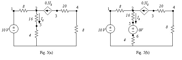
The voltage source VN that mentions the controlling current must be an independent source, and it can have a zero or finite value. If the current through a resistor controls the source, a dummy voltage source of 0V value should be connected in series with the resistor to monitor the controlling current.
For example, if the current source of Fig. 4(b) is controlled by the current of 16 ohm resistor’s current as shown in Fig. 5(a), we can redraw the circuit as shown in Fig. 5(b) and write the Net list.
# Current-controlled voltage source (CC VS)
The symbol of a Current-controlled voltage source (CC VS) is shown in Fig 6(a). N+ and N- are the positive and negative nodes, respectively, of the voltage source. VN is a voltage source through which controlling current flows. The controlling current is assumed to flow from the positive node of VN through the voltage source VN to the negative node of VN.

The voltage source VN that mentions the controlling current must be an independent source, and it can have a zero or finite value. If the current through a resistor controls the source, a dummy voltage source of 0V value should be connected in series with the resistor to monitor the controlling current.
The description of CC VS is
H<name> N+ N- VN g (trans resistance value)
Typical statement
H1 1 2 V1 4
The statement means that the CC VS H1 is connected between nodes 1 and 2 and its voltage is controlled by the voltage source V1’s current. The trans resistance value is 4.
# Spice Schematics
In spice schematics, the dependent sources can be found in the parts list. Click on the get parts list and write E(for VACS) in the part name box. Now, click the place & close option to work with the VCVS. You can get the other type of dependent sources by writing F,G or H) in the part name box. The parts are the following shapes

The circular box represents the source and the other terminals are for the controlling parameter.
The circuit in fig 1(b) can be drawn in schematics in the following way

To set the gain value, click the VCVS or select it and double click. The part attributes option will be activated. Click on the gain option and the write the gain value on the value box. Click the save At tr. and then click OK.

Fig-9
The circuit in Fig. 3 can be drawn in the following way

Fig-10
For a circuit with multiple number of dependent sources and mesh. The inter connection of the controlling nodes may become complicated. To make the interconnections easier, a connection bubble named Bubble can be used.
To work with the bubble connector, click on the add new parts option and write b on the parts name box. Then select bubble from full list column. Now, click the place and close option to work with the connection bubble.
Place the bubble in one corner of the interconnection and double click it. In the set attributes option write a in the label box and click ok. Copy the bubble in the other corner of the interconnection. The connection is then automatically made; you need not have to draw the wire to complete the connection. Similarly you can connect another bubble with different label for another interconnection. The circuit in Fig. 1 can be drawn with bubble in the following way

Fig-11
The circuit in Fig 4can drawn as
chung cư newskyline
ReplyDeletedịch vụ làm báo cáo tài chính
chung cư hateco hoàng mai
chung cư hà nội
dịch vụ hoàn thuế gtgt
dịch vụ kế toán thuế trọn gói
dịch vụ quyết toán thuế
khoá học kế toán thuế
trung tâm kế toán
dịch vụ báo cáo thuế
dịch vụ kế toán nội bộ
dịch vụ dọn dẹp sổ sách kế toán
chung cư eco green city
kế toán cho giám đốc
khoá học kế toán tổng hợp
khoá học kế toán excel
forum rao vat
mu private
trung tâm dạy kế toán tại tphcm
dịch vụ kế toán trọn gói
------------------------------------------------------------------------
Cánh gà nướng
11-11-2008, 09:12 PM
Bá Y Thiên Hạ
Tác giả : Độc Cô Lãnh Giả
Chương 4 : Nhân tích sơ hiện lưỡng câu thương
[Hiện ra dấu vết con người
Ngờ đâu hai kẻ đồng thời bị thương]
Dịch : workman
Biên tập : ndphong91
Nguồn : Tàng Thư Viện
"Tiểu Bạch đáng chết, dám đánh lén ta ! Ủa mà có chuyện gì thế? Làm sao
trong đầu mình dường như lại hiện ra mộ